Monday 18 June 2012

Upper Wishbones, Vertical Link and Spring

Catching up on the blog yesterday gave me new impetus to get back out into the garage and crack on with the rest of the suspension.

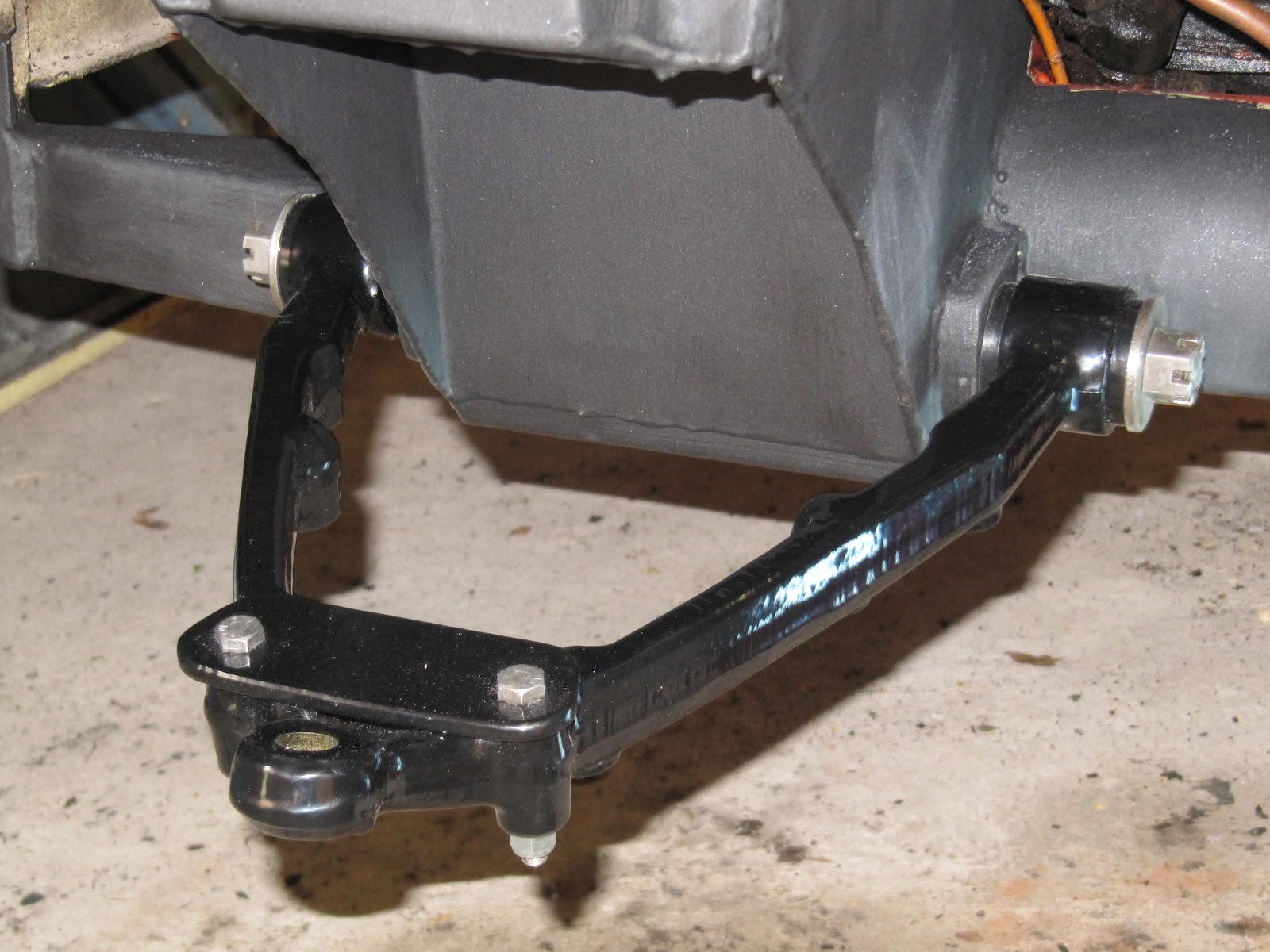
The rebuilt upper wishbones were fitted. Note that the upper wishbones on a MK11 have to be rebuilt onto the upper fulcrum before the fulcrum is fitted to the chassis due to not being able to fit the left wishbone over the fulcrum when fitted due to a chassis support arm.

The vertical link and new upper ball joint could then be installed to connect upper and lower wishbones. To ensure that when the suspension is in the correct position when standing on the wheels the suspension was set up so that the upper bump stop is not resting on the chassis. I left a few centimetres gap.

Now the bit that I have been dreading, compressing the new spring and fitting the spring pan. I have created a home made spring compressor as traditional spring compressors will not fit. It's a Jensen, why would traditional tools work!.

The home made compressor is made up of an inch thick aluminium disk that fits in the underside of the spring pan. The disk has a 20mm hole in the centre in which a 16mm high tensile threaded bar can pass through the inside of the spring and , using 2 M24 nuts, locked off at the top using the shock mounting hole.

There is another M24 under the disk that can be would up the threaded bar and thus compressing the spring.

To guide the pan into the right position on the lower wishbone I used two 6" 3/8 Bolts in the front left and back right spring pan fixing holes into the upper wishbone.

What followed was 30 minutes of slowly winding up the spring hoping that the nut doesn't lock on or de-thread the bar! Surprisingly it worked rather well and as soon as the pan was close enough to the wishbone the 4 free fixing bolts were fitted and used to secure the pan. The guide bolts were removed and the remaining two bolts were fitted. These bolts were then tightened slowly a bit at a time working around the pan until all tightened correctly.

The spring compressor could then be loosened off. At this point the whole suspension initially lowers until the bump stop is resting on the chassis. The suspension will rise when the wheel is on and is taking the weight of the car.

Time for pictures...


Front suspension with spring installed


Shock installed

Sunday 17 June 2012

Front Suspension rebuild - Part 1

Finally at the point where I can start putting parts back on the car. All of the parts that were removed (wishbones etc) have been powder coated and new springs and shocks have been purchased.


Powder coated parts and new shocks

I also decided to replace nuts and bolts where replacements can be found. As usual Appleyards came up with the goods and an Imperial Assorted Garage Pack of nuts, bolts and washers in various sizes was sourced as well as various non standard bolts. Not all of the bolts could be found so the old ones were scrubbed and the threads cleaned.

Before each part is put back on the car the holes and threads need to have the powder coating removed. To confirm each hole and thread is ready I did a test build of the part on the bench.


Lower wishbone

The lower wishbone is now back on. Next is the upper wishbone assembly and vertical link. Then the dreaded spring and spring pan. I am not looking forward to that bit at all. 

Chassis Paint

Work has taken it's toll recently so there has been very little work done on the Interceptor or on the blog! I have managed to spend a few evenings on it with the following results....

A couple of coats of undercoat and top coat. I have selected a couple of products from a local company called Dacrylate Paints. The undercoat is Vinaprime and the top coat is Vinadac. Very impressed with the products and results so far.


Undercoat on Chassis


Top coat on Chassis

This is the turning point as I can now start putting suspension parts back on.


Wednesday 28 March 2012

...More cleaning

Hours and hours of cleaning later, the wheel well is starting to look in a position to re-paint.

Starting to remove the old stone chip...


The task gets larger...


Anti roll bar removed...it will be going for powder coating.


With all the stone chip removed...


A few more hours on the cross beam should see this section ready for painting....I think it's still fun :)

Sunday 26 February 2012

Chassis Cleaning

The full extent of the crap and crud on the chassis can now be seen since the suspension is removed.

A full 5 hours of cleaning this morning has revealed that the chassis is actually bright red! I thought it was oil coloured!

There is no magic method that I have found for cleaning oil and crud off. I resorted to Gunk degreaser (not sure if it's the best but it worked for me), a wire brush and lots of paper towel. Then it's just down to elbow grease and patience.

5 hours into the cleaning it looks better, but still plenty to go.


I think I will have to spend quite a few more hours on cleaning before its acceptable. I also think I might have to take the radiator out to complete it properly.

I also need to find out if it needs fully repainting or if cleaning and touching up is enough. There are a few very small areas back to bare metal so something will have to be done, either patch it up or full coat over the whole area. I'll take advice from the JOC forum.

While cleaning I noticed that one of the rubber hoses is damaged. It looks like it has been rubbing on the top right upper fulcrum bolts. There is quite a big area of damage so needs replacing. Another job to the list


Front Suspension Teardown - Catalogue of parts

Dismantling the suspension would have been impossible without the Interceptor parts catalogue. It is worth every penny that it cost to buy from the JOC website. The exploded diagrams are extremely useful, as are the tables of parts.

As each part (washer, nut, screw, plate etc) was removed from the car it was put in a plastic bag with a tag showing the workshop manual item number, description and code id. This will then be used to ensure re-assembly goes smoothly. Well that's the plan anyway!

The major parts (wishbones etc) will now go off for cleaning and powder coating and the calipers are heading off for a clean, repaint, rebuild and pressure test. The calipers will get new pistons and seals at the same time. The only choice is what colour caliper paint to go for, silver, gold, red or black. I'm thinking black at the moment but I've got a few days to decide.

Front Suspension Teardown - Upper Wishbone Assm

The first part I removed from the upper wishbone assembly was the upper ball joint. This is held on by 2 bolts and these came out with relative ease.

However, the remaining upper wishbone assembly is slightly more difficult to remove. Access to the left side nut  on the upper fulcrum bar is not possible due to a chassis post so I decided to remove the remaining assembly in one go by removing the bolts that hold on the upper fulcrum shaft.

These are not easy to access as they are on the back of the suspension mount and could only be removed using a spanner and turning at a 1/4 of a turn at a time. It was a very slow process and must have taken over an hour for the 4 bolts!

Once all 4 bolts had been removed the assembly could be rotated by 90 degrees so that it could be lifted over the top of the suspension mount.

The split pins and nuts could then be removed from the fulcrum shaft. I had loosened these while the assembly was still fixed to the car. The lower wishbone arms are then free to be removed from the shaft. Again the bushes will be replaced before re-assembly.

The workshop manual shows 1 packing plate on the left side and 3 on the right side of the fulcrum shaft mounting. For some reason there were only 2 plates, one on each side. I will have to do further investigation before re-assembly to determine if this is correct or if I need to source 2 more plates.

Front Suspension Teardown - Lower Wishbone

The lower wishbone is relatively simple to remove. The split pins and nuts are removed from each end of the lower fulcrum shaft. The fulcrum shaft can then be pushed through the chassis mount until the wishbone is freed.

The fulcrum shaft was pushed through using a length of bar and pushed from the front of the car to the back. The Wishbone is then free from the car.


The wishbone bushes will be extracted later and replaced when the wishbone is refurbished.

Front Suspension Teardown - Vertical Link

Now that the spring has been removed the vertical link can be taken out. The vertical link connects the upper and lower wishbones and houses the stub axel.

The vertical link was removed by undoing the nuts from the upper ball joint and the lower cap and socket. The cap and socket was then removed from the bottom and the vertical link is then lowered off the upper wishbone.


Bottom view of cap and socket

The stub axel could not be prised from the vertical link so it was removed still in place. I'll let you know later if this was a mistake or not!


Vertical link with stub axel attached

Front Suspension Teardown - Shock and Spring


The shock absorber was then removed by unlocking the top nuts on the shock and then removing the 4 bolts on the plate holding the shock to the spring pan at the bottom. The shock can then be dropped through the bottom of the suspension. The shock absorber is in pretty bad shape and will be replaced.

The anti roll bar was then dis-connected from the spring pan using the ball joint scissors.

Now to the tricky bit, removing the spring and spring pan. I was not looking forward to this at all and can safely say I did not enjoy one minute of the process! There is a lot of tension in the spring even when the suspension is in it's lowest position. There is not enough access to use conventional spring compressors so another method had to be found.

A conversation with Andy and Kevin at Appleyards determined that Jensen used to have a specific tool for this job which consisted of a threaded bar and large metal plate that sits under the spring pan. The threaded bar goes up inside the spring where the shock was and is locked off using the shock mounting on the chassis. There is a large nut under the metal plate that can be used to lower the spring pan when the pan fixing bolts are removed. 

Now, getting one of these original tools is pretty much impossible so I had to fashion my own. The plate was made out of inch thick circular aluminium with a diameter that fits snugly in the underside of the pan in the recessed area. This plate had a 17.5mm hole drilled in the centre. I purchased the threaded bar and nuts from a local fastener company. The bar was 1m long and 15mm diameter. I reasoned that I needed around 600mm for the spring to fully de-compress so I cut it down. The car had to be jacked up really high as the bar has to be inserted from the bottom up into the spring. I used a couple of large washers and then used 2 nuts to lock it off in the same way the shock is fixed.

The plate was then loaded onto the bar and held under the pan using a large washer and a nut. I only tightened the nut finger tight. 

Now, the worst bit. I then started undoing the 6 pan fixing screws. I unscrewed half a turn each and then moved to the next screw and moved clockwise around the pan. As more pressure was placed on the nut holding the plate I loosened it slightly so that it did not become too tight under the plate due to the tension in the spring. I followed this routine until the screws could be removed. Even with the plate there was still a lot of tension on the screws and I got a terrific shock from the noise as the first screw came loose and the plate moved. I slowly made my way back across the garage (from where I had jumped to) to inspect why. It then dawned on me that as the suspension is in it's fully down position the pan is not parallel to the floor so the back of the pan needed to be dropped down first. Knowing this made it a little easier so I continued removing the screws until all had been removed and the plate was taking the strain. The nut could then be slowly unscrewed which lowered the pan and removed the tension in the spring. When all the tension is out of the spring the lock nuts could be removed from the top of the threaded bar and the spring and pan removed.

I was really pleased with how this worked out as, although nerve racking, it was actually pretty simple to get the spring off the car using this tool.

Front Suspension Teardown - Process and Hub

So far it has taken around a month to strip down the near side front suspension. The main delay was due to having to find a suitable way of removing the spring. I'll cover this later in the post.

The teardown was performed in the following order:-

1, Remove hub assembly
2, Remove shock absorber
3, Pan and spring lowered
4, Remove vertical link
5, Lower wishbone assembly removal
6, Upper wishbone assembly removal

The first job was to remove the hub assembly. This involved removing the brake caliper which is held on by 2 bolts onto the brake caliper bracket. Then the hub cap and nut could then be removed and the hub and disk assembly pulled from the stub axel. The disk can be separated later and checked to see if it is suitable to be re-used.


The stub axel and brake caliper bracket can be seen in the above photo.

The brake hose was then removed from its mount on the vertical link.

Next job is shock, spring pan and spring.


Monday 30 January 2012

Rack off

A good few hours under the Jensen resulted in the steering rack exiting the vehicle.

This is where having the right tools for the job make things immeasurably easier. In this case a good set of heavy duty ball joint scissors. I had to use the breaker bar as well as the ball joints were well and truly locked on. They made one hell of a crack when they popped!

After the ball joints it was fairly easy to undo the lower of the two universal joints on the steering column. The next problem arose with removing the bottom two hoses that connect the rack to the pump. The left one came off easily, the second one not so. The nut would not spin on the hose resulting in the hose rotating in the socket. There was nothing for it but to wait until the rack was more accessible before removing the final hose.

Next the four bolts holding the rack in were removed. As a pointer to how dirty the underside of the car is I couldn't actually see the heads of the left side bolts due to being covered in oil and crud. Once cleaned they came off easily.

To remove the rack I also had to remove the cross member fan bracket to allow more clearance. The rack was then fed out of the passenger side wheel arch until the rack could then be lifted up and out of the engine bay. This was a two person job so the Wife was called from the house to get her hands dirty! She doesn't like the car now!

I could now see why the hose would not come off. The metal end of the hose had been bent which would not allow the nut to spin. Using a persuader it was straightened and the nut then could be easily undone. I will evaluate whether this hose needs replacing later when the rack goes back in.

While dropping the old rack off at Appleyards I discovered that it is possible to refurbish the universal joints of the column so this is another job on the list. The bottom joint is always at angle and is prone to wear so this seems a sensible job to do while the rack is out.


I have given the UJ a quick clean but I will finish the job when fully refurbishing.

One final decision made this weekend is to not put the new rack straight in. I cannot put a brand new part into a car so covered with oil and crud that it will be covered in the first 100 miles. Therefore I have decided to refurbish the front suspension and fully clean up the front end.


Target is to complete this before the summer. Might be a bit optimistic but you can see from the above photo why it's required.

Wednesday 25 January 2012

Aaarrgghh - sheered wheel lug

Well work put paid to being able to spend any time whatsoever on the Interceptor over Christmas. A last minute rush project for a customer meant all Christmas in front of the laptop instead of being under the bonnet.

I finally got out into the garage 2 weekends ago to set about the steering. Started with the simple job of jacking the car up and removing the wheels. Well I though it would be simple until disaster struck and I sheered the top off one of the wheel lugs.


Now, I didn't think I was being particularly brutal with it, I was only using a socket on a breaker bar so I was very surprised this happened. Having spoken to few people and doing some research on the internet I think what has happened is that as the lug has been on and off the car many many times over the years and the threads on the stud have spread and finally it locked the lug the last time it was tightened.


As you can see, there is a fair amount of lug left inside the wheel.

Having mused over how to recover this situation for a number of hours I felt the only way really to get the wheel off was to drill the remaining parts of the lug out of the wheel.

Many hours of careful drilling (and drill bits!) later the remaining part of the lug loosened and I was able to remove it. Basically it took 2 weekends to remove the wheel....rubbish. Admittedly I got very frustrated at various times and headed back into the house to do something else to avoid causing more damage to the car in a fit of anger. Oh well, it's all character building and I can now get on with the real job of removing the rack.